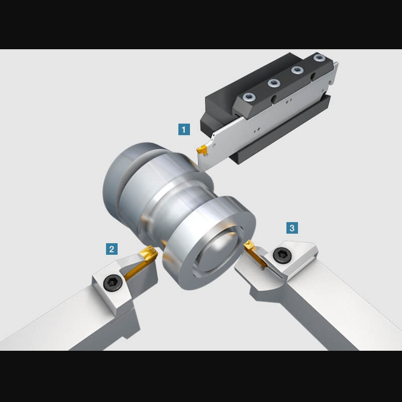
Grooving inserts are essential in machining operations, particularly for creating precise grooves or channels on a workpiece. These inserts are classified into two main categories: internal grooving inserts and external grooving inserts, each designed for specific applications. Understanding their differences is crucial for selecting the right tool for your machining needs.
| Type | Description | Applications |
|---|---|---|
| Internal Grooving Inserts | Designed to cut grooves inside a cylindrical workpiece or borehole. | Commonly used in automotive, aerospace, and hydraulic systems for creating O-ring grooves or internal channels. |
| External Grooving Inserts | Engineered to cut grooves on the outer diameter of a cylindrical or round workpiece. | Widely applied in industries requiring precise external threading, snap ring grooves, or decorative patterns. |
| Aspect | Internal Grooving Inserts | External Grooving Inserts |
|---|---|---|
| Size and Geometry | Typically smaller with a compact design to fit inside boreholes. | Larger in size, designed for open and accessible areas on the workpiece. |
| Shank Design | Longer and narrower to reach deeper into the bore without interference. | Shorter and sturdier for enhanced stability during external cuts. |
| Cutting Edge | Engineered for inward-facing cuts, often with sharper angles for precise internal grooves. | Optimized for outward-facing cuts with robust edges to handle higher external cutting forces. |
| Aspect | Internal Grooving Inserts | External Grooving Inserts |
|---|---|---|
| Tool Holder | Requires specialized boring bars or holders to fit within narrow spaces. | Uses standard tool holders or external grooving tool adapters. |
| Vibration Control | More prone to vibrations due to long overhangs; dampened boring bars are often necessary. | Less prone to vibrations; shorter tool length enhances stability during machining. |
| Parameter | Internal Grooving Inserts | External Grooving Inserts |
|---|---|---|
| Cutting Speed | Lower cutting speeds recommended to reduce heat and vibration in confined spaces. | Higher cutting speeds achievable due to better cooling and chip evacuation. |
| Chip Evacuation | Challenging due to limited space; requires precise cutting parameters and coolant application. | Easier chip evacuation, aided by gravity and open space around the cutting area. |
| Surface Finish | Demanding to achieve due to difficulty in tool alignment and restricted access. | Easier to achieve smooth finishes on external surfaces. |
| Feature | Internal Grooving Inserts | External Grooving Inserts |
|---|---|---|
| Material | Typically carbide with advanced wear resistance for machining confined spaces. | High-strength carbide or cermet materials to handle external machining forces. |
| Coating | Often coated with TiN, TiCN, or AlTiN for heat resistance and prolonged tool life. | Coated similarly but may also include wear-resistant layers optimized for external machining. |
The table below summarizes the main differences between internal and external grooving inserts for quick reference:
| Criteria | Internal Grooving Inserts | External Grooving Inserts |
|---|---|---|
| Primary Use | Internal grooves in boreholes | External grooves on outer diameters |
| Design | Compact, narrow, and inward-facing cutting edges | Larger, robust, and outward-facing cutting edges |
| Stability | More prone to vibration | Higher stability |
| Cutting Speed | Lower | Higher |
| Chip Control | Challenging | Easier |
Selecting the correct type of grooving insert depends on your specific machining requirements, material properties, and desired outcomes. By understanding these distinctions, manufacturers can ensure precision, efficiency, and durability in their machining operations.
Contact person: Steve Lee
E-mail: [email protected]
Phone: 86-731-22200908
Address: Floor 4,Building NO.15,Zhichuang Plaza,NO.1299,Liyu Road,Tianyuan District,Zhuzhou City, Hunan, P.R. CHINA
Tel:0086-19973342799
E-mail: [email protected]

WeChat Official Account